

When an RC phase shift oscillator employs an op-amp in its circuit, it becomes an electronic oscillator with a stable sine wave output. It functions by developing two groups of 180-degree phase shifts, one via the RC network and the other via an op-amp in an inverting circuit. Due to this phase shift arrangement, it produces nearly pure sinusoidal signals with extreme frequency stability and finds a good application in audio processes, signal generation, as well as other electronic systems requiring precise AC signals.
Using an RC phase shift oscillator and op-amp offers better control than transistor-based designs as it has improved accuracy of frequency, amplitude stability, and less loading effects. The following explains the complete circuit diagram with working principles, mathematical derivations, and application details
Apart from generating the sine wave output, they are also used to provide significant control over the phase-shifting process. Other usages of phase shift oscillators are:
- In audio oscillators
- Sine Wave Inverter
- Voice Synthesis
- GPS units
- Musical Instruments.
Before we start designing the RC phase shift oscillator, let's learn more about its phase and phase shift.
Table of Contents
- What is Phase Shift in RC Oscillator Circuits?
- RC phase shift oscillator
- └ Phase Shift in RC Networks
- Working of RC Phase Shift Oscillator
- └ Oscilloscope Analysis of Phase Shifts
- Key Circuit Components
- Circuit Diagram
- Simulation
- Frequency of Oscillation Derivation
- Advantages
- Troubleshooting Common Issues
- Frequently Asked Questions
- Explore More
What is Phase Shift in RC Oscillator Circuits?
A phase is a full cycle period of a sinusoidal wave in a 360-degree reference. A complete cycle is defined as the interval required for the waveform to return to its arbitrary initial value. Phase is denoted as a pointed position on this waveform cycle. If we see the sinusoidal wave, we can easily identify the phase.
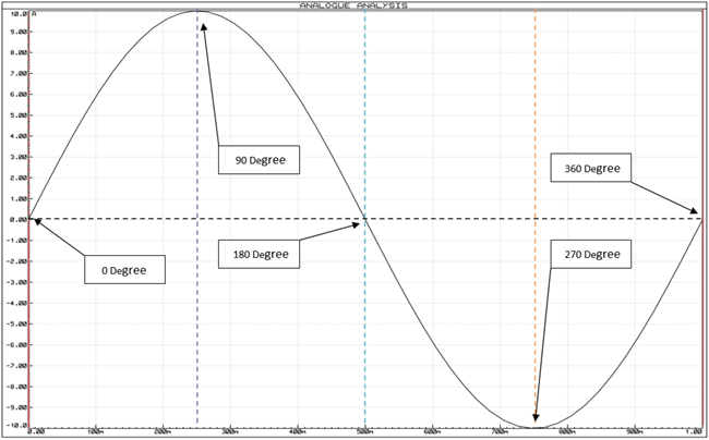
In the above image, a complete wave cycle is shown. The initial starting point of the sinusoidal wave is 0 degrees in phase, and if we identify each positive and negative peak and 0 points, we will get 90, 180, 270, and 360-degree phases. So, when a sinusoidal signal starts its journey other than the 0-degree reference, we call it a phase shift differentiating from the 0-degree reference.
For sinusoidal signals, 360° means one complete wave cycle. While working with RC circuits, we observe:
At 0° phase: The waveform starts from zero and moves to positive amplitude
At 90° phase: The waveform is at its maximum positive amplitude
At 180° phase: The waveform goes back to zero while moving negatively
At 270° phase: The waveform reaches the greatest negative amplitude
At 360° phase: The waveform finishes one complete cycle
If we see the next image, we will identify what a phase-shifted sinusoidal wave looks like…
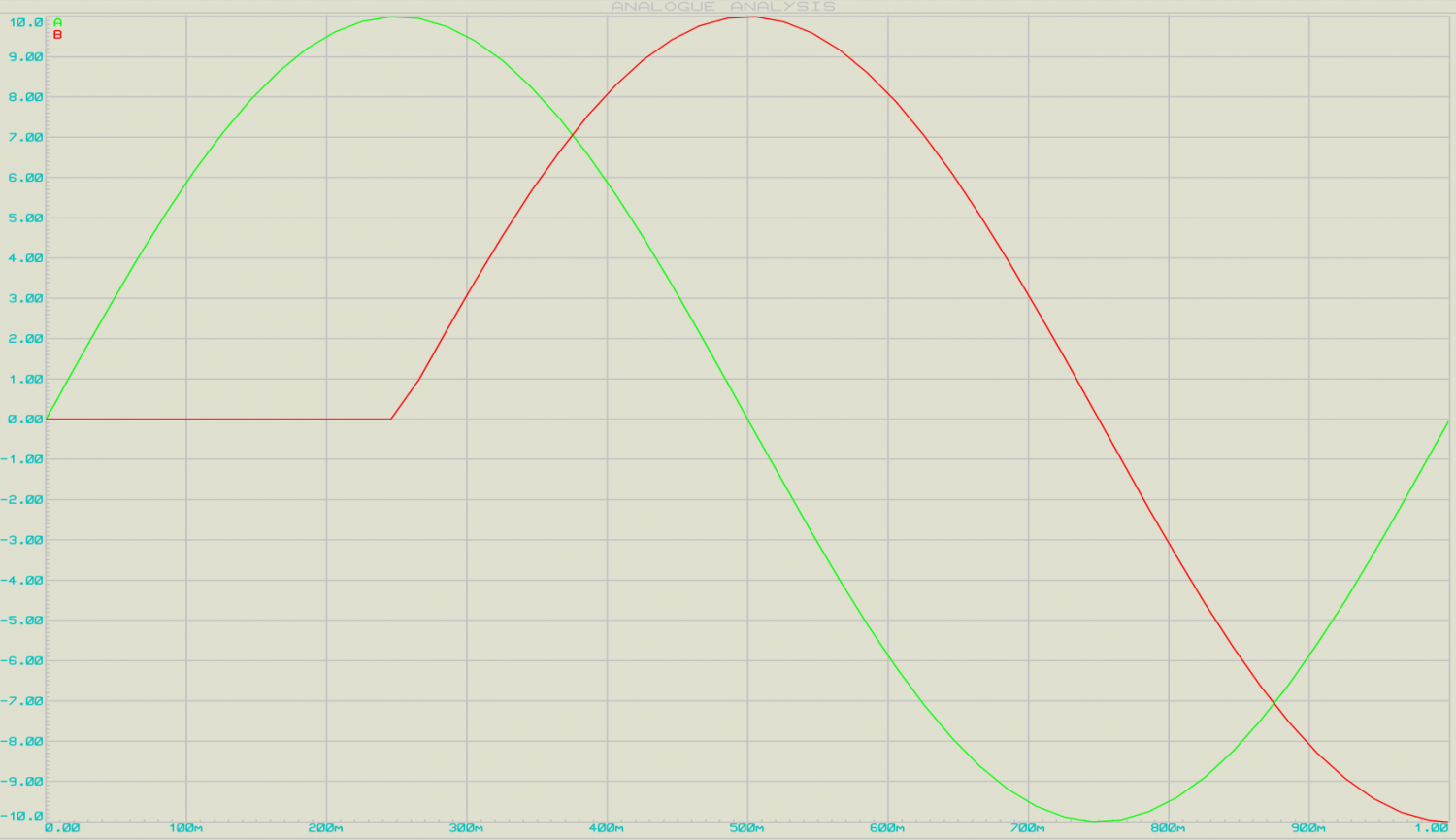
In this image, there are two AC sinusoidal signal waves presented, the first Green Sinusoidal wave, is 360 degrees in phase, but the red one is 90 degrees phase shifted out of the green signal.
This phase shifting can be done using a simple RC network.
RC phase shift oscillator using op amp
A simple RC phase shift oscillator provides a minimum phase shift of 60 degrees.
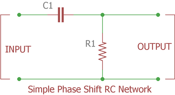
The above image shows a single-pole phase shift RC network or ladder circuit, which shifts the phase of the input signal equal to or less than 60 degrees.
Phase Shift in RC Networks
Ideally, the phase shift of the output wave of an RC circuit should be 90 degrees, but in practice it is approximately. 60 degrees, as the capacitor is not ideal. The formula for calculating the phase angle of the RC network is mentioned below:
φ = tan-1(Xc / R)
Where Xc is the reactance of the capacitor and R is the resistor connected in the RC network.
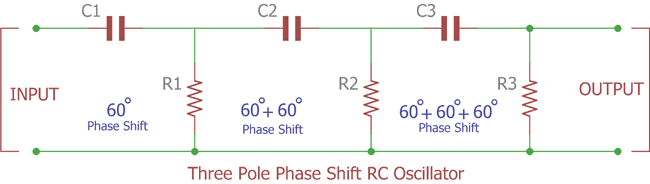
If we cascade there RC network, we will get a 180-degree phase shift.
Now to create oscillation and sine wave output, we need an active component, either a Transistor or an Op-amp in inverting configuration.
If you want to learn more about the RC Phase Shift Oscillator, then follow the link
Why use an Op-amp for an RC Phase Shift Oscillator instead of a Transistor?
There are some limitations in using a Transistor for building an RC Phase Shift Oscillator:
- It is stable for low frequencies only.
- RC phase shift oscillator requires additional circuitry to stabilise the amplitude of the waveform.
- Frequency accuracy is not perfect, and it is not immune to noisy interference.
- Adverse Loading Effect. Due to cascade formation, the second pole’s input impedance changes the resistance properties of the first pole filter. The more filters cascaded, the worse the situation worsens, as it will affect the accuracy of the calculated phase shift oscillator frequency.
Due to the attenuation across the resistor and the capacitor, the loss across each stage is increased, and the total loss is approximately 1/29th of the input signal.
As the circuit attenuates at 1/29th, we need to recover the loss. Learn more about them in our previous tutorial.
Working of RC Phase Shift Oscillator Using Op-Amp
When we use an op-amp for an RC phase shift oscillator, it functions as an inverting amplifier. Initially, the input wave is introduced into the RC network, due to which we get a 180-degree phase shift. And, this output of RC is fed into the inverting terminal of the op-amp.
Now, as we know that the op-amp will produce a 180-degree phase shift when it functions as an inverting amplifier. So, we get a 360-degree phase shift in the output sine wave. This RC phase shift oscillator, using an op-amp provides a constant frequency even under varying load conditions.
Oscilloscope Analysis of Phase Shifts
Measurement Point | Phase Shift | Signal Characteristics |
|---|---|---|
After the 1st RC Stage | 60° | Sine wave with slight attenuation |
After the 2nd RC Stage | 120° | Further attenuated sine wave |
After the 3rd RC Stage | 180° | Significantly attenuated, phase-shifted sine wave |
Op-Amp Output | 360° (0°) | Amplified sine wave, original phase restored |
Key Circuit Components for RC Phase Shift Oscillator Circuit
- Op-Amp IC – LM741
- Resistor – (100k – 3nos, 10k – 2nos, 4.7k)
- Capacitor – (100pF – 3nos)
- Oscilloscope

RC Phase Shift Oscillator Using Op-amp Circuit Diagram

Simulation of RC Phase Shift Oscillator using Op-Amp
RC phase shift oscillator provides an accurate sine wave output. As you can see in the simulation video, in the end, we have set the probe of the oscilloscope to four stages of the circuit.
Oscilloscope Probe | Wave Type |
First – A | Input Wave |
Second – B | Sine wave with 90 degree Phase Shift |
Third – C | Sine wave with 180 degree Phase Shift |
Fourth – D | Output Wave (Sine wave) with 360 degree Phase Shift |
Here, the feedback network is offering a phase shift of 180 degrees. We are getting 60 degrees from each of the RC networks. And, the remaining 180-degree phase shift is generated by the op-amp in the inverting configuration.
Frequency of Oscillation Derivation
For calculating the frequency of oscillation, use the following formula:
F = 1 / 2πRC√2N
Advantages of the RC Phase Shift Oscillator Using OP AMP
The RC Phase Shift Oscillator was said to have a mighty few advantages while using the op-amp in comparison with the one with the conventional transistor:
• High input impedance: Does not load the RC network.
• Low output impedance: Delivers a stable output voltage regardless of the load change.
• Good frequency stability: The Frequency of oscillation is constant.
• Low harmonic distortion: Sinusoidal output free from harmonics.
• Temperature stability - Less variation with temperature.
Practical Applications
• Audio signalling: Musical instruments and audio testing
• Function Generators: Lab and test uses
• Clock Generation: To generate timing for digital systems accurately
• Commercial Setups: Local oscillator and carrier generator
• Medical Units: Therapeutic and diagnostic
Troubleshooting Common Issues
Problem | Possible Cause | Solution |
|---|---|---|
No oscillation | Insufficient gain | Increase the feedback resistor value |
Frequency deviation | Component tolerance | Use precision components |
Distorted output | Excessive gain | Reduce the feedback resistor value |
Unstable oscillation | Poor power supply | Add decoupling capacitors |
Frequently Asked Questions
⇥ Why does the RC phase shift oscillator must provide a 360-degree phase shift?
RC phase shift oscillator must provide a 360-degree phase shift to secure the satisfaction of the Barkhausen criterion required for oscillation. The 360 degrees of shift is equivalent to zero degrees of shift-the feedback signal is therefore in phase with the input signal. This positive feedback thereby satisfies the conditions for sustained oscillations if coupled with sufficient gain, without requiring an external input signal
⇥ What is the minimum gain needed for an RC phase shift oscillator?
The minimum gain needed for the RC phase shift oscillator is 29. This is because the three-stage RC network of feedback reduces the signal by a factor of 1/29. The op-amp should deliver at least such gain to counteract the attenuation and achieve sustained oscillation as per the Barkhausen criterion.
⇥ What are the uses of an RC phase shift oscillator using an op-amp?
Applications of the RC phase shift oscillator with an op-amp are:
- Audio signal generators and musical instruments
- Function generators for equipment testing
- Sine wave inverters for power supply
- Voice synthesis equipment
- GPS devices and communication equipment
- Clock generation for digital circuitry
- Medical and therapy equipment
⇥ How does an RC phase shift oscillator using an op-amp operate?
RC phase shift oscillator using an op-amp operates by:
- Three RC networks achieve 180° phase shift (60° each)
- An op-amp in inverting mode introduces an additional 180° phase shift
- Total 360° phase shift meets oscillation requirements
- An op-amp amplifies a reduced signal from an RC network
- Positive feedback ensures sustained oscillation
Explore More Oscillator Circuits
Expand your knowledge of waveform generation by diving into these related oscillator designs. Each circuit showcases a unique approach to frequency generation.

The Hartley oscillator is one of the LC type feedback oscillator which is invented in 1915 by the American engineer Ralph Hartley. In this tutorial, we will discuss about the construction and application of Hartley oscillator.

Same as other oscillators Colpitts oscillator consists of a gain device, and the output is connected with an LC circuit feedback loop. The Colpitts oscillator is a linear oscillator which produces a sinusoidal waveform.

A resistor and capacitor is required to produce a phase shift, and If we connect an amplifier in inverting spec and connect the amplifier and RC networks with a feedback connection the output of the amplifier start to produce a sinusoidal waveform by oscillation.

what is the purpose of R5 in this circuit?
Thank you,