
If you've ever worked with the GSM SIM800L module, you know that it can be a powerful tool for various projects, including making calls, sending SMS, and even accessing the internet through GPRS. However, like any technology, it's not immune to issues. In this blog, we'll walk you through how to interface sim800l with Arduino Uno and provide troubleshooting tips to help you get it up and running smoothly. Previously, we have also interfaced the SIM800L with ESP32, you can also check that out if you are interested. Additionally, once you have mastered this basic interfacing, you can explore our other projects, such as the Arduino GPS Tracker, GSM-Based Home Automation, DIY IVR Phone Call System, and Portable Internet for Raspberry Pi, among others.
Before diving into troubleshooting, let's cover some fundamental aspects of the GSM module.
Interfacing the GSM Module with Arduino
Build Time: 6-8 hours | Cost: $20-40 | Difficulty: Intermediate
What You'll Learn: Learn UART serial communication, AT command programming, voltage level shifting, GSM/GPRS module configuration, SMS handling, call management, power supply management, and network status monitoring.
Applications: Enables IoT remote monitoring, SMS-based alerts, automated call systems, vehicle tracking, home automation, remote data logging, and emergency notifications.
Table of Contents
- Understanding GSM SIM800L Module Basics
- GPRS vs GSM: SIM800L Module Capabilities
- GSM Module SIM800L Pin Diagram
- SIM800L Technical Specifications
- SIM800L GSM Module Power Requirements & Connection
- SIM800L GSM Module Connection With Arduino UNO
- Building a Circuit in the SIM800L GSM Module With Arduino
- SIM800L GSM Is Not Working?
- How to Insert a SIM Card in the SIM800L
- SIM800L Network Status LED Indication
- Sim800L Not Connecting To The Network
- SIM800L AT Command Test
- Sending SMS in SIM800L GSM Module Working
- SIM800L GSM Module Arduino Code
- Making Calls on SIM800L Using Arduino
- Technical summary and GitHub Repository
- People Also Ask Questions on GSM Module with Arduino
- Build More With GSM
Understanding GSM SIM800L Module Basics
GSM, which stands for Global System for Mobile, is a cellular standard primarily designed for mobile communication. GSM is a standard developed to facilitate communication between mobile devices. It's a digital cellular network technology that enables users to make calls, send texts, and access basic data services like SMS (Short Message Service) and MMS (Multimedia Messaging Service). GSM networks operate on various frequency bands globally, allowing for international roaming capabilities for mobile subscribers..
GPRS vs GSM: SIM800L Module Capabilities
GPRS, which stands for General Packet Radio Service. GPRS is an enhancement of the GSM standard that enables mobile data transmission. It introduces packet-switched technology to GSM networks, allowing for faster data transfer rates compared to traditional circuit-switched methods. GPRS enables features like internet browsing, email access, and other data-intensive applications on mobile devices. It optimizes network resources by only using bandwidth when data is being transmitted, making it more efficient for data communication than its predecessor.
Feature | GSM | GPRS |
| Acronym | Global System for Mobile Communications | General Packet Radio Service |
| Technology | Circuit-switched | Packet-switched |
| Voice Communication | Primary focus: supports voice calls and SMS | Secondary, supports voice but is optimized for data |
| Data Transmission | Initially designed for voice, supports data with added functionality | Optimized for data transmission |
| Data Speed | Up to 9.6 kbps | Typically up to 114 kbps (2.5G), later enhancements offer higher speeds |
| Connection Duration | Always-on connection for voice calls | On-demand connection, data sessions initiated as needed |
| Billing | Billed based on usage (calls and SMS) | Billed based on data transferred, usually in kilobytes or megabytes |
| Network Architecture | Traditional cellular network with a voice-centric focus | Overlay on GSM network, utilizing existing infrastructure for data services |
| Application | Voice calls, SMS, low-bandwidth data applications | Internet browsing, email, multimedia messaging, mobile apps, IoT connectivity |
GSM Module SIM800L Pin Diagram
The SIM800L module is a GSM/GPRS module that offers a wide range of functionalities. It resembles a small chip with an antenna connector and various pins. The image below shows the GSM module SIM800L pin Diagram, which will later be useful when we are connecting the SIM800L GSM module with Arduino.
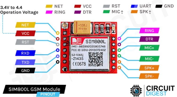
What we are particularly interested in are the pins on the left side of this, including VCC, GND, TX, and RX. These pins play a crucial role in its operation.
SIM800L Technical Specifications
» Supply Voltage: 3.7V - 4.2V DC
» Maximum Supply Current: 2A (during transmission)
» Communication: UART serial communication with the embedded SIM900 command set
» Supported Networks: 2G GSM/GPRS
» AT Commands: AT command set
» Compatible with Arduino: Compatible with all Arduino boards with serial communication.
SIM800L GSM Module Power Requirements & Connection
One essential aspect is providing a stable power supply. The SIM800L module requires an input voltage of 3.7V to 4.2V, which can be different from what you usually encounter in electronics.
You can either use a buck converter with 2A or more max current capacity, which is set at 4V, or a 3.7V li-ion battery to meet this requirement.
Important notes: The current capacity of the buck converter is mentioned as greater than or equal to 2A because the GSM module is a power-hungry device, specifically when sending messages or calls. Adding a capacitor between VCC and GND can further stabilize the power supply, but the module works without that, too.
SIM800L GSM Module Connection With Arduino UNO
The complete SIM800L Arduino circuit is given below. If you're using the SIM800L with a microcontroller like an Arduino, you'll need to be mindful of voltage compatibility. The module operates at 3.3V, while many microcontrollers, like Arduino, work at 5V internally. Ensure proper level-shifting to prevent damage to the module. A voltage divider is often necessary when transmitting data from the microcontroller to the module.

You can see in the above sim800l arduino wiring diagram that I've used one 10k resistor and one 20k resistor in series to create a voltage divider and convert the 5V to 3.3V, but you can use different values too. I've used a voltage divider calculator to figure out the resistor values. You can try changing the values, too.
Building a Circuit in the SIM800L GSM Module With Arduino
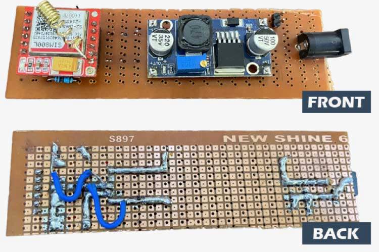
Create a proper circuit SIM800L GSM module connection, including the necessary wiring between your microcontroller and the SIM800L module. Check for any loose connections, as even a small oversight can lead to issues. I’ve created a small circuit which looks like the image below, but this step is really not mandatory, as it will work without soldering. Just check the jumper connections properly.
SIM800L GSM Is Not Working?
At this point, let's assume that you have made all the connections right and you powered the SIM800L GSM module, but the module does not work. So, let's address common issues you might encounter while working with the SIM800L module when you power it on.
How to Insert a SIM Card in the SIM800L
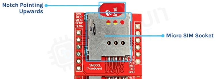
Remember that the SIM800L is designed to work with 2G SIM cards. If your SIM800L is not detecting a SIM, make sure your SIM card is compatible with this module and inserted correctly. It should look like this.
Even after inserting it and correcting if your SIM800L is not detecting the SIM card, the problem could be with the power supply or your circuit connections. You can know if your SIM card is being detected by looking at the network status LED, as shown below.
SIM800L Network Status LED Indication
The SIM800L module features a network status indicator LED, which blinks at different rates to indicate the network state.

Blink Every One Second

Blink Every Two Sec

Blink Every Three Sec
- A fast blink (once every second) suggests that the module is running but hasn't connected to the cellular network.
- A slower blink (once every two seconds) indicates an active GPRS data connection.
- The desired state for this tutorial is one blink every three seconds, indicating that the module can send and receive voice and SMS.
Sim800L Not Connecting To The Network
If the network status LED on sim800L is not blinking as explained above, it means that the SIM800 GSM module is not connecting to the network. In this case, follow these steps below:
Check if the 2G supported SIM card( with recharge for call and sms) is correctly inserted, and the SIM connector or the SIM card is not damaged or broken.
Increase the voltage supplied by the buck converter, but don't exceed the module's maximum voltage of 4.2V.
Verify if other SIM cards from the same network have proper coverage in your location. If not, change the SIM Card and Retry.
If the problem persists, the SIM800L module might be faulty and should be replaced.
Another commonly asked question regarding the SIM800L module is that, does sim800l supports 4G?
Well, the answer is NO. The Sim800L module only supports 2G; it does not provide support for 3G and 4G. Meaning if you are in India, the only two options you have are Airtel and Vodafone.
Note:- Don't move beyond this point if you are not getting a blink every 3 seconds. Even after following all these steps, if the SIM800L module is not registering with the network, then there is something wrong with the module, and you should try changing it.
SIM800L AT Command Test
Uploading an AT command test program to your Arduino allows you to communicate with the SIM800L module. The easiest way to test if your SIM800L GSM module is working or not is by using a simple AT command test. The image below shows how the SIM800L is powered, and the LED blinks once every 3 seconds to indicate that it is ready with the network. Then, by sending a simple AT command, we can check if the GSM module is giving OK
Make sure you have uploaded the code below to your Arduino before sending commands to the SIM800L module. Alternatively, you can also use a USB to TTL converter in place of the Arduino and test for the same.
// Create a SoftwareSerial object to communicate with the SIM800L module
SoftwareSerial mySerial(3, 2); // SIM800L Tx & Rx connected to Arduino pins #3 & #2
void setup()
{
  // Initialize serial communication with Arduino and the Arduino IDE (Serial Monitor)
  Serial.begin(9600);
  // Initialize serial communication with Arduino and the SIM800L module
  mySerial.begin(9600);
  Serial.println("Initializing...");
  delay(1000);
  mySerial.println("AT"); // Handshake test, should return "OK" on success
  updateSerial();
  mySerial.println("AT+CSQ"); // Signal quality test, value range is 0-31, 31 is the best
  updateSerial();
  mySerial.println("AT+CCID"); // Read SIM information to confirm whether the SIM is inserted
  updateSerial();
  mySerial.println("AT+CREG?"); // Check if it's registered on the network
  updateSerial();
}
void loop()
{
  updateSerial();
}
void updateSerial()
{
  delay(500);
  while (Serial.available())
  {
    mySerial.write(Serial.read()); // Forward data from Serial to Software Serial Port
  }
  while (mySerial.available())
  {
    Serial.write(mySerial.read()); // Forward data from Software Serial to Serial Port
  }
}
Ensure that the module responds with "OK" to confirm its responsiveness. If this is working for you and you are feeling adventurous, you can also test the Call and SMS capability in the same setup by just typing in a different command
If your SIM800L is not responding, double-check the RX and TX connections, and also try reversing them briefly to see if the serial monitor displays any changes.
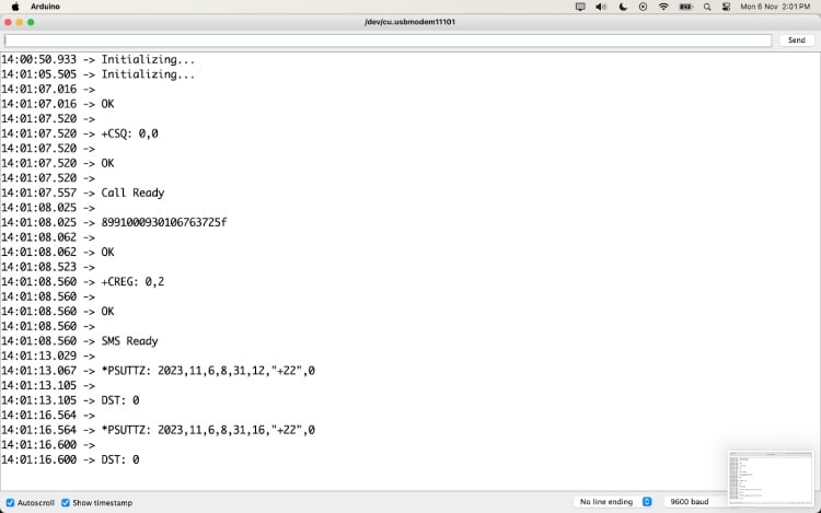
If you get the above results on your serial monitor. You can move forward to making calls and messages. If you are curious, you can also visit the SIM800L AT commands manual to check out all the possible AT commands available on the SIM800L GSM Module.
Sending SMS in SIM800L GSM Module Working
The SIM800L module supports making calls and sending messages.
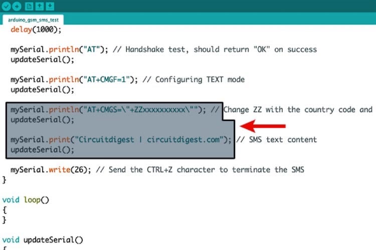
Below is the Arduino code for sending a message on the SIM800L. You just need to change the phone number (+XXXXXXXXXXXX)and the text that you need to send, and upload the code.
SIM800L GSM Module Arduino Code
Here’s the complete SIM800L SMS Arduino code for the same.
#include <SoftwareSerial.h>
// Create a SoftwareSerial object to communicate with the SIM800L module
SoftwareSerial mySerial(3, 2); // SIM800L Tx & Rx connected to Arduino pins #3 & #2
void setup()
{
  // Initialize serial communication with Arduino and the Arduino IDE (Serial Monitor)
  Serial.begin(9600);
  // Initialize serial communication with Arduino and the SIM800L module
  mySerial.begin(9600);
  Serial.println("Initializing...");
  delay(1000);
  mySerial.println("AT"); // Handshake test, should return "OK" on success
  updateSerial();
  mySerial.println("AT+CMGF=1"); // Configuring TEXT mode
  updateSerial();
  mySerial.println("AT+CMGS=\"+ZZxxxxxxxxxx\""); // Change ZZ with the country code and xxxxxxxxxxx with the phone number to send an SMS to
  updateSerial();
  mySerial.print("Circuitdigest | circuitdigest.com"); // SMS text content
  updateSerial();
  mySerial.write(26); // Send the CTRL+Z character to terminate the SMS
}
void loop()
{
}
void updateSerial()
{
  delay(500);
  while (Serial.available())
  {
    mySerial.write(Serial.read()); // Forward data from Serial to Software Serial Port
  }
  while (mySerial.available())
  {
    Serial.write(mySerial.read()); // Forward data from Software Serial to Serial Port
  }
}
If your SIM800L is not sending SMS, check with the SIM card network provider if 2G SMS is available on their network.
Making Calls on SIM800L Using Arduino
Now, let’s test the call feature. Copy and paste the code given below and change the phone number given in the code (+XXXXXXXXXXXX) with your recipient's number.
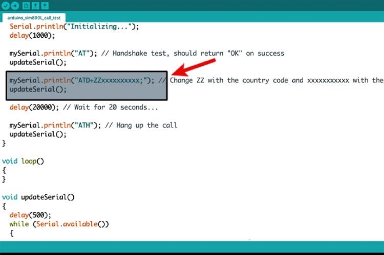
Here’s the complete SIM800L GSM module Arduino code where you need to make the changes.
#include <SoftwareSerial.h>
// Create a SoftwareSerial object to communicate with the SIM800L module
SoftwareSerial mySerial(3, 2); // SIM800L Tx & Rx connected to Arduino pins #3 & #2
void setup()
{
  // Initialize serial communication with Arduino and the Arduino IDE (Serial Monitor)
  Serial.begin(9600);
  // Initialize serial communication with Arduino and the SIM800L module
  mySerial.begin(9600);
  Serial.println("Initializing...");
  delay(1000);
  mySerial.println("AT"); // Handshake test, should return "OK" on success
  updateSerial();
  mySerial.println("ATD+ZZxxxxxxxxxx;"); // Change ZZ with the country code and xxxxxxxxxxx with the phone number to dial
  updateSerial();
  delay(20000); // Wait for 20 seconds...
  mySerial.println("ATH"); // Hang up the call
  updateSerial();
}
void loop()
{
}
void updateSerial()
{
  delay(500);
  while (Serial.available())
  {
    mySerial.write(Serial.read()); // Forward data from Serial to Software Serial Port
  }
  while (mySerial.available())
  {
    Serial.write(mySerial.read()); // Forward data from Software Serial to Serial Port
  }
}
Now, upload the code and your recipient should receive a call.
Note:- You can reset the Arduino to make the call again. The same goes for messages
Technical summary and GitHub Repository
Here’s the GitHub repo where you can find the complete code and the circuit diagram. We have also provided an overview of a project's key components, implementation details, and functionality, typically covering the hardware/software architecture and design decisions that we have used in this tutorial.


People Also Ask Questions on GSM Module with Arduino
⇥ Does the SIM800L support 4G?
No, the SIM800L GSM module supports 2G only. It does not support 4G or 3G. This means that if you are in a country where 2G is being removed, then you will need to consider using different GSM modules.
⇥ What to look into if the SIM800L GSM module does not connect?
If your SIM800L GSM module is not connecting to the network, then check for: 1) Make sure you are using a 2G compatible SIM card, 2) Check the power supply at 3.7V-4.2V with a capacity of 2A, 3) Check that the antenna is connected, 4) Make sure that 2G is available in your area.
⇥ Which Arduino boards will work with the SIM800L GSM module?
The GSM SIM800L module is compatible with every Arduino board. You can use SIM800L with boards like Arduino Uno, Nano, Pro Mini, Mega, ESP32/ESP8266, and more. Just remember to level shift the voltage to users who utilise 5V Arduino boards.
⇥ Is the SIM800L GSM module suitable for Internet of Things projects?
Yes, the SIM800L GSM module's operating principle makes it ideal for IoT projects that need cellular connectivity, remote monitoring, SMS alerts, and data logging to cloud servers.
With the right knowledge and troubleshooting techniques, you can make the SIM800L module work seamlessly for your projects. By understanding its basics and addressing common issues, you'll be well-equipped to harness the full potential of this versatile GSM/GPRS module.
Now that you have got your SIM800L GSM module working, you can check out the SMS SMS-based vehicle Tracking project, the Automated Call Answering Machine, and the Forest Fire warning Project that we built earlier. Happy tinkering!
Build More With GSM
Take the next step by exploring real-world projects that put GSM communication to use. From tracking GPS locations to automating home appliances and building your own IVR system, these projects help reinforce what you've learned and apply it creatively.
Arduino Location Tracker using SIM800L GSM Module and NEO-6M GPS Module
This comprehensive project shows you how to create a fully functional GPS tracking system using Arduino UNO R3, SIM800L GSM module, and NEO-6M GPS module, a perfect low-cost DIY combination for vehicle monitoring, asset protection, or personal safety applications.

GSM Based Home Automation using Arduino
In this project, no Smart phone is needed, just the old GSM phone will work to switch ON and OFF any home electronic appliances, from anywhere.
 Device using Raspberry Pi")
Low-Cost Interactive Voice Response (IVR) Device using Raspberry Pi
In this project, we will be interfacing SIM800L with Raspberry Pi and we will be making automated phone calls and sending automated messages using it.

How do I connect to the Internet as the continuity of the sim800L module you can find a short code for this.. thanks